PiStorm68Kv1.8
PiStorm68K board, rendered from native CAD on a dark studio floor

PRECISION ARRAYS / THE PISTORM68K PROJECT

Classic bus.
New possibilities.

The physical 68000 bus.
A Raspberry Pi connection.

An EPM570 CPLD, four 16-bit latches and a selectable 68000 path. Explore the AmiCube PiStorm68K board, its regulated Pi supply and original printed enclosure.

68000 BUS / CPLD / RASPBERRY PIv1.8 hardware
01 — THE IDEAScroll to discover ↓Native CAD · Blender studio render
EPM570MAX II CPLD
68000Selectable physical CPU path
145.93 × 98.25Board footprint · millimetres
06Copper layers

02 / HARDWARE EXPLORER

Turn it around.
Take it apart.

Explore the native KiCad board and separate its component groups. Switch to the printed enclosure to lift its cover, or inspect the separate holder.

PISTORM68K / NATIVE BOARDThe heart of the project.145.93 × 98.25 mm PCB · 6 copper layers
Preparing the hardwareLoading native CAD geometry…
Native KiCad geometry
Drag to orbit · Scroll / pinch to zoom · Right-drag to pan
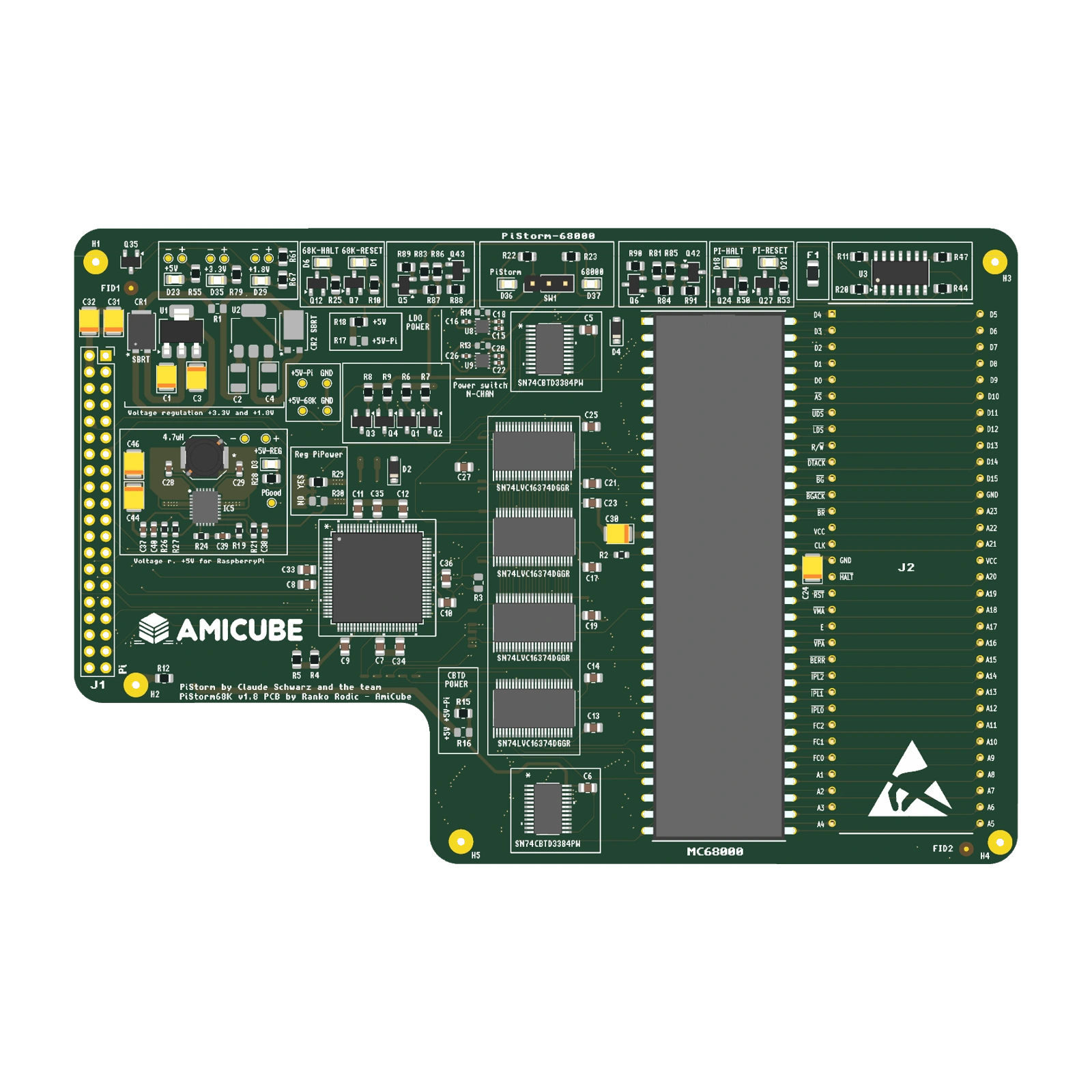
Native v1.8 board, including the EPM570, four latches, 68000 interface and regulated Pi supply.Geometry exported from the saved design

The board Inspect native geometry and printed markings.

Component groups Lift the upper parts and inspect the connections.

Printed enclosure Explore the original case and holder.

03 / THE ARCHITECTURE

A familiar bus.
New possibilities.

Follow the 68000 interface through the CPLD, latches and translation circuitry, then explore the board’s power paths and physical connections.

PISTORM68K / FUNCTIONAL DESIGNTHE 68000 INTERFACE
Functional paths · selected interfaces shown

The EPM570 CPLD coordinates the Pi and 68000 interface. Four SN74LVC16374 devices latch bus signals, while two SN74CBTD3384 devices provide the translation path.

FOLLOW THE DESIGN

A bridge across the bus.

The EPM570 CPLD coordinates the Pi and 68000 interface. Four SN74LVC16374 devices latch bus signals, while two SN74CBTD3384 devices provide the translation path.

CPLD configuration and Pi software define the accelerator behaviour.

One board.
Distinct roles, working together.

Explore a functional view of the design, then return to the native model to see the components themselves.

BENEATH THE COMPONENTS

6 copper layers.
A foundation for every signal.

Six copper layers carry the CPU interface, GPIO and supply networks. The saved layer names identify ground, signal and power roles.

Signals Ground Signals / power
Open the native stackup drawing ↗
PCB CROSS-SECTIONTOP ↓ BOTTOM
  1. 01F.CuSignals / components
  2. 02In1.CuGround reference
  3. 03In2.CuSignals
  4. 04In3.CuPower distribution
  5. 05In4.CuSignals
  6. 06B.CuGround / signals
Dielectric separates the copper layers · thickness exaggerated

04 / THE ENCLOSURE

The original enclosure.
Built around the board.

Explore the saved printed case, its engraved cover and the separate holder. Each model comes from the original PiStorm68K FreeCAD project.

Lift the lid. See the interface. — PiStorm68KPRINTED / CASE

NATIVE FREECAD · BASE + COVER

Lift the lid. See the interface.

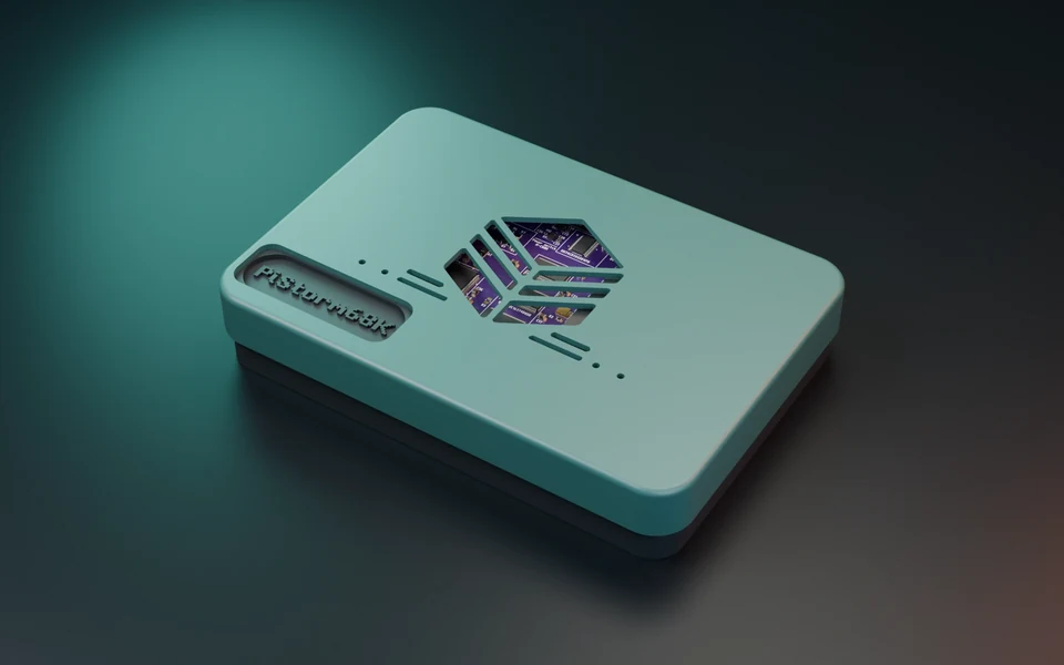
The shaped base follows the board outline. The removable cover carries the original engraved AmiCube mark and opens to reveal the board inside.

Case envelope
159.75 × 111.91 × 29 mm
Construction
Printed base + engraved cover
Source
Original Case.FCStd
Open the board guide ↗
A supporting piece of the design. — PiStorm68KPRINTED / HOLDER

NATIVE FREECAD · SEPARATE SUPPORT

A supporting piece of the design.

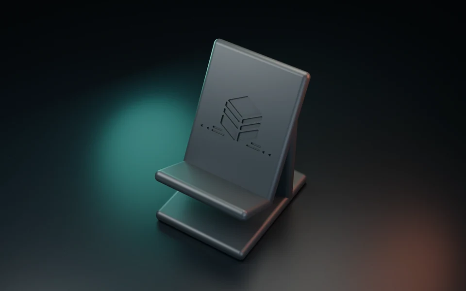
The separate holder is retained in the original case project. Inspect its shape and mounting features as an independent part.

Saved envelope
62 × 78.01 × 92.36 mm
Construction
Single printed holder
Source
Original Holder body
Open the board guide ↗
ORIGINAL GEOMETRY

Designed as a set.

The enclosure view combines the original base and cover with the current detailed KiCad board. The holder is shown separately in its own view.

PRINTED IDENTITY

The mark is part of the cover.

The cover retains the original recessed AmiCube artwork from the saved FreeCAD model.

Original enclosure CAD. The saved case reference used a 1.51 mm PCB; the current board is 1.6 mm. XY placement follows the reference board, but current physical fit and connector clearances have not been requalified.

05 / THE ASSEMBLY BOOK

Good design.
Down to the details.

Start with top assembly, then turn the board over and explore its stackup, routing and power guides.

Open the 5-page board guide ↗

SELECT A DRAWING

Native engineering drawings
Development documentation

01 / 05

Board / top assembly

06 / WHERE WE ARE

Real hardware.
A continuing story.

CURRENT BOARD SNAPSHOT

PiStorm68K / v1.8

The saved six-layer board, with its physical 68000 path, Raspberry Pi header and CPLD interface.

Native KiCad placement and printed markings.
ORIGINAL PRINTED ENCLOSURE

Base, cover and holder

The existing FreeCAD case project supplies the enclosure and separate holder shown here.

The cover retains the original engraved AmiCube artwork.
EXPLORE THE INTERFACE

Power. Select. Connect.

Review the CPU/Pi selection circuitry, power options and assembly drawings before integrating the board.

Hardware modes depend on the configured CPLD and Pi software.
PiStorm68Kv1.8

Classic bus. New possibilities.

Explore the hardware ↑
Assembly drawingOpen PDF ↗
Enlarged assembly drawing

Use the PDF for vector detail and printing.