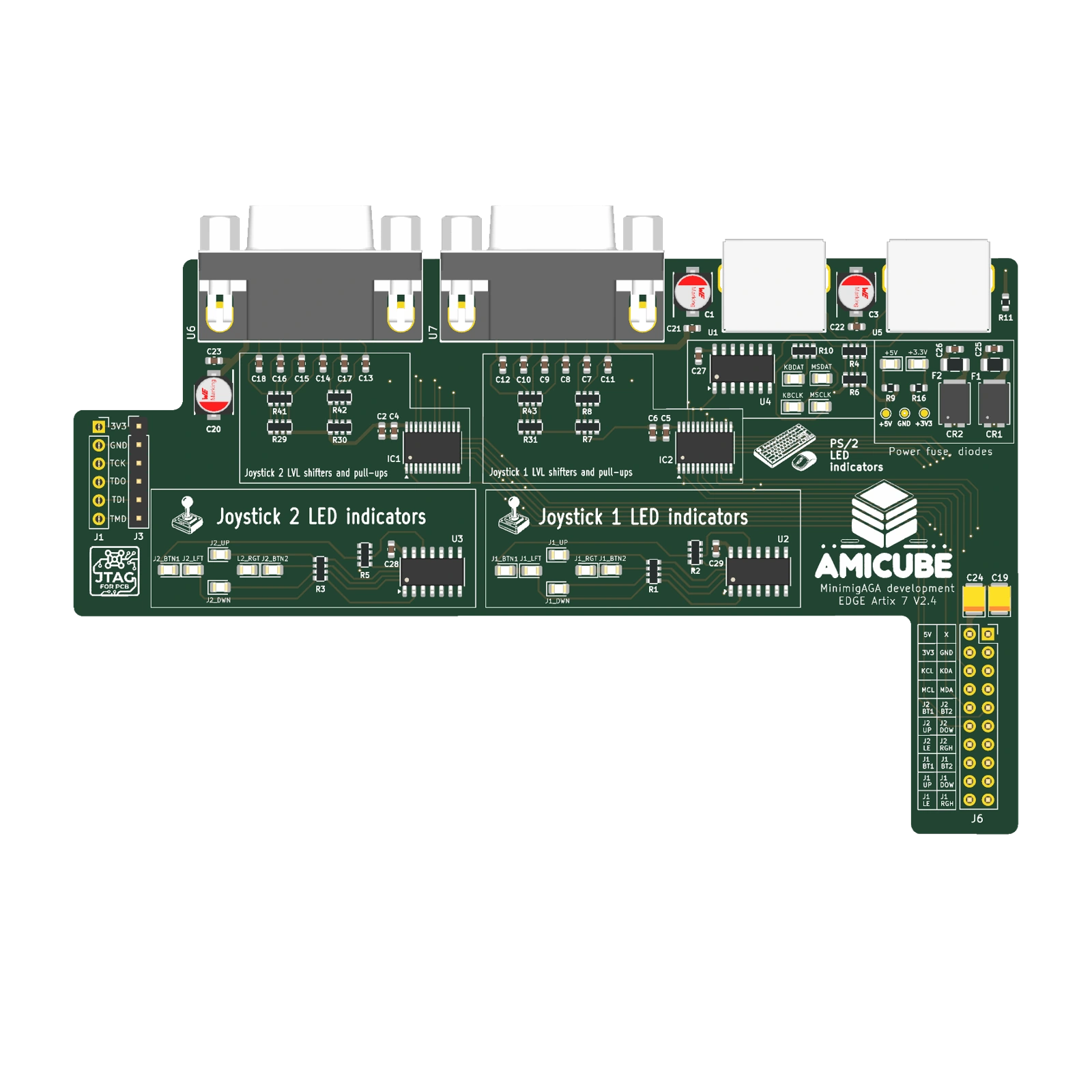
 BOARD / TOP
NATIVE GEOMETRY · COMPONENT SIDE
Connections in plain sight.
Native DEV1 v2.4 board, including dual DB9, dual PS/2, translators, filters and activity LEDs.
- PCB outline
- 130.32 × 79.44 mm
- Board thickness
- 1.6 mm
- Copper layers
- 4
 Edge-PMODDEV1 · v2.4

PRECISION ARRAYS / THE EDGE-PMOD PROJECT
Two joysticks. Keyboard. Mouse.
One development interface.
Dual DB9 joystick ports, separate PS/2 keyboard and mouse connections, level translation and activity indicators. Meet the AmiCube Edge Artix-7 development interface.
02 / HARDWARE EXPLORER
Explore EDGE + PMOD together, then separate the two boards. Inspect the native PMOD design or the reconstructed EDGE baseboard on its own.
Interactive 3D is unavailable. Explore the native renders and assembly drawings below.
View assembly guide ↓Native PMOD The original KiCad geometry and printed markings.
Two boards Use Separate boards or the lift slider to reveal EDGE below.
EDGE facsimile Reconstructed from photos; dimensions and connector fit are approximate.
03 / THE ARCHITECTURE
Follow the joystick and PS/2 paths to the host header, then inspect the translation, filtering and activity indication around them.
The two DB9 ports pass through filtering and SN74CBTD3384 translation to the 3.3 V joystick signals at the 20-pin host header. Direction and button lines also feed activity indicators.
FOLLOW THE DESIGN
The two DB9 ports pass through filtering and SN74CBTD3384 translation to the 3.3 V joystick signals at the 20-pin host header. Direction and button lines also feed activity indicators.
Functional paths group related circuitry; see the board guide for assembly detail.
Explore a functional view of the design, then return to the native model to see the components themselves.
BENEATH THE COMPONENTS
A four-layer, 1.6 mm PCB connects the external ports to the development header. The native stackup guide records the copper and dielectric arrangement.
04 / THE PHYSICAL DESIGN
Use the native top and bottom views to inspect the physical layout, connector access and mounting before returning to the interactive model.
BOARD / TOPNATIVE GEOMETRY · COMPONENT SIDE
Native DEV1 v2.4 board, including dual DB9, dual PS/2, translators, filters and activity LEDs.
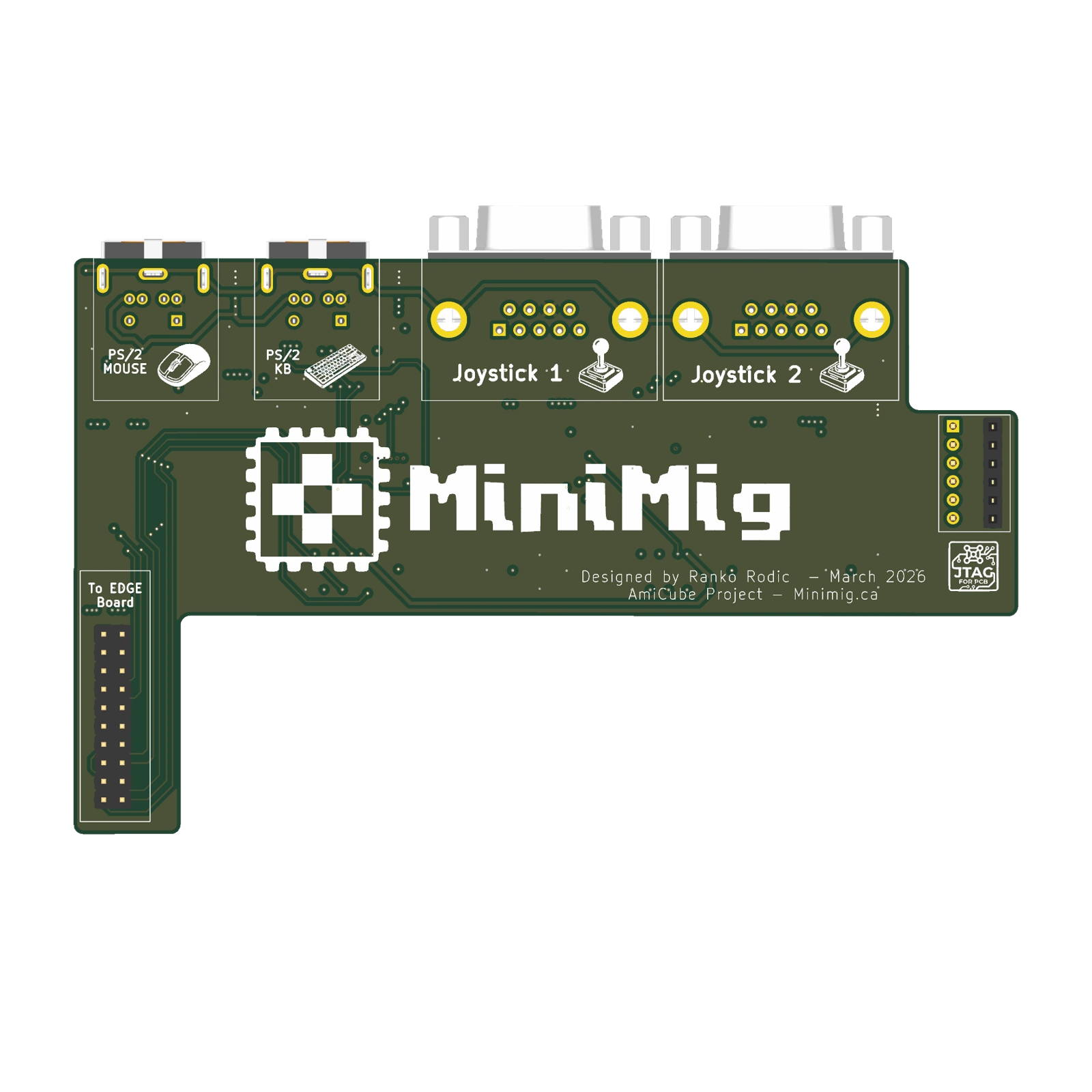 BOARD / UNDERSIDE
NATIVE GEOMETRY · REVERSE SIDE
The underside view preserves the native pads, mounting holes and printed markings. The assembly book shows the corresponding reference drawing.
The shaped Edge interface carries its external ports along the top edge and the host connection on the projecting end.
The 3D model includes the native projecting connectors. The PCB outline dimensions exclude those projections.
The physical design views show the current board. No separate enclosure CAD is included in this project presentation.
05 / THE ASSEMBLY BOOK
Start with top assembly, then turn the board over and explore its stackup, routing and power guides.
Open the 5-page board guide ↗06 / WHERE WE ARE
The Edge Artix-7 development interface, with two joystick ports and separate keyboard and mouse connectors.
Native four-layer PCB geometry.Joystick direction/button indicators and PS/2 clock/data indicators help show activity at the board.
The silkscreen labels the signals beside their indicators.The 20-pin host connection carries input signals and supply rails. The separate six-pin pair provides a pass-through connection.
Match the documented connector pinout to the target system.