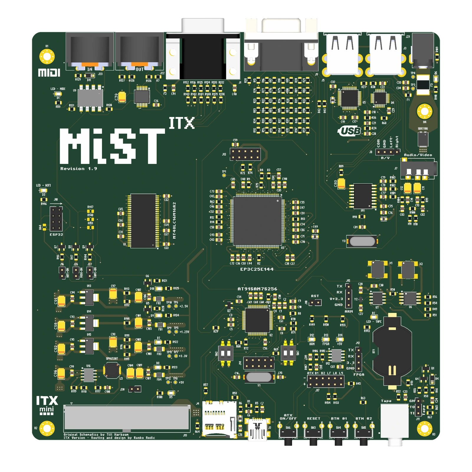
 BOARD / TOP
NATIVE GEOMETRY · COMPONENT SIDE
Connections in plain sight.
Native v1.9 Mini-ITX board, including Cyclone III, SDRAM, ARM control, USB, MIDI and analogue media interfaces.
- PCB outline
- 170 × 170 mm
- Board thickness
- 1.6 mm
- Copper layers
- 6
 v1.9
v1.9

PRECISION ARRAYS / THE MIST ITX PROJECT
FPGA computing.
A full Mini-ITX footprint.
A Cyclone III FPGA, 32 MiB of SDRAM and an ARM controller, surrounded by USB, MIDI, video, audio and expansion connections. Explore MiST in its ITX form.
02 / HARDWARE EXPLORER
Explore the native KiCad board and separate its component groups. Turn the board over, inspect the connections and show or hide its original silkscreen.
Interactive 3D is unavailable. Explore the native renders and assembly drawings below.
View assembly guide ↓The board Inspect native geometry and printed markings.
Component groups Lift the upper parts and inspect the connections.
The drawings Five sheets cover assembly, stackup, routing and power.
03 / THE ARCHITECTURE
Explore the FPGA and memory, then follow the video, sound, controller and peripheral paths across the ITX board.
The Cyclone III EP3C25 FPGA connects to a 16M × 16-bit SDRAM device, giving 32 MiB of memory. Dedicated clocks and an AT91SAM7S256 controller support configuration and system I/O.
FOLLOW THE DESIGN
The Cyclone III EP3C25 FPGA connects to a 16M × 16-bit SDRAM device, giving 32 MiB of memory. Dedicated clocks and an AT91SAM7S256 controller support configuration and system I/O.
The loaded FPGA core and controller firmware determine system behaviour.
Explore a functional view of the design, then return to the native model to see the components themselves.
BENEATH THE COMPONENTS
Six copper layers provide the routing and ground references for the FPGA, SDRAM and peripheral circuits. The saved layer names mark In1.Cu, In3.Cu and B.Cu as ground layers.
04 / THE PHYSICAL DESIGN
Use the native top and bottom views to inspect the physical layout, connector access and mounting before returning to the interactive model.
BOARD / TOPNATIVE GEOMETRY · COMPONENT SIDE
Native v1.9 Mini-ITX board, including Cyclone III, SDRAM, ARM control, USB, MIDI and analogue media interfaces.
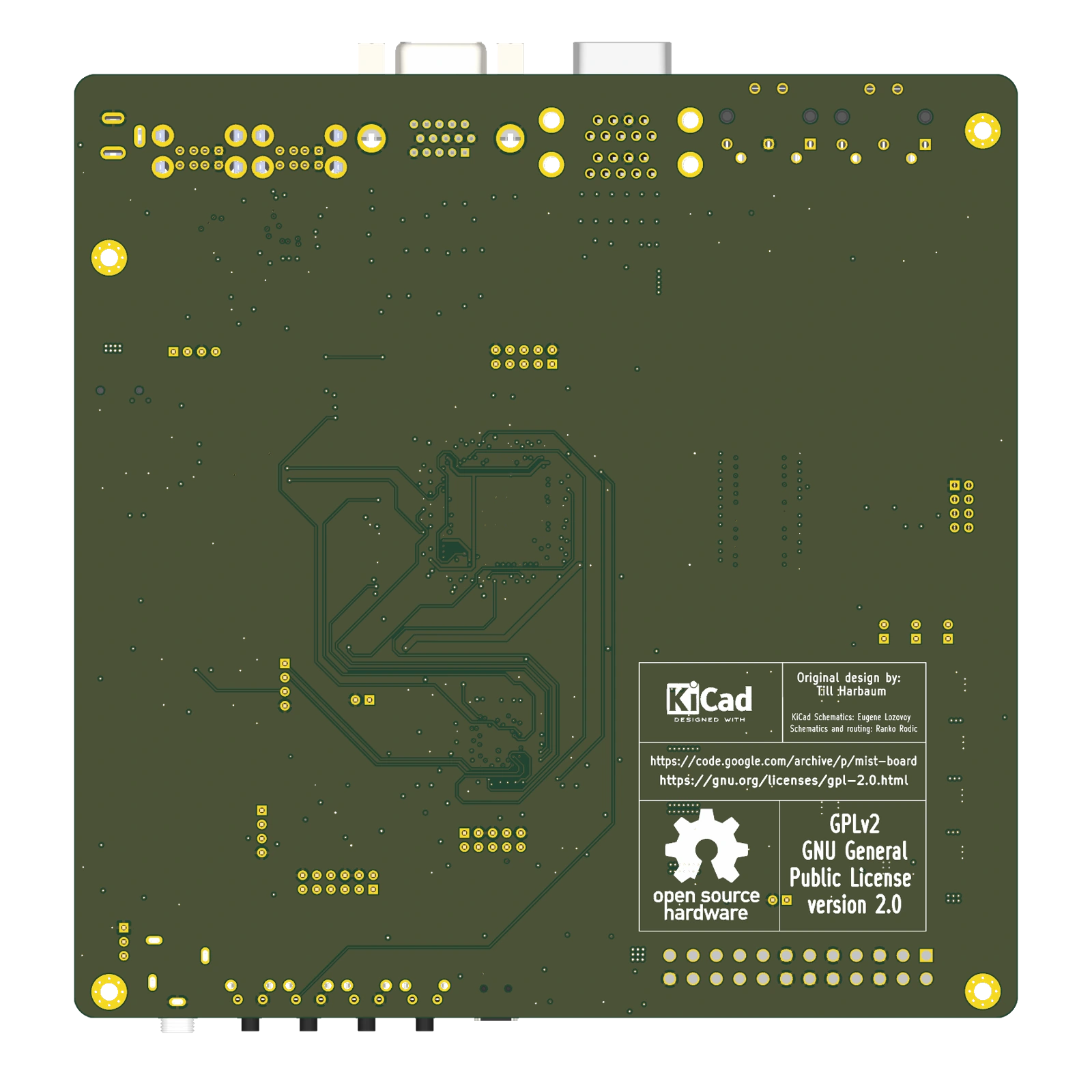 BOARD / UNDERSIDE
NATIVE GEOMETRY · REVERSE SIDE
The underside view preserves the native pads, mounting holes and printed markings. The assembly book shows the corresponding reference drawing.
The 170 × 170 mm board combines rear-edge connectors with front-panel, power and service access.
The 3D model includes the native projecting connectors. The PCB outline dimensions exclude those projections.
The physical design views show the current board. No separate enclosure CAD is included in this project presentation.
05 / THE ASSEMBLY BOOK
Start with top assembly, then turn the board over and explore its stackup, routing and power guides.
Open the 5-page board guide ↗06 / WHERE WE ARE
The saved 170 × 170 mm board combines Cyclone III logic, SDRAM and an AT91SAM7S256 controller.
Native six-layer PCB geometry and silkscreen.Four USB-A ports, two DB9 joystick ports, MIDI in/out, VGA, analogue A/V, tape and service headers surround the board.
The connector tour groups every external port and header.FPGA core and controller firmware determine which machines and peripheral features are available.
Use the assembly book to inspect the hardware behind each function.