AMICUBE — original stacked cube logov1.2
AmiCube v1.2 motherboard, rendered from native CAD on a dark studio floor

PRECISION ARRAYS / THE AMICUBE V1.2 PROJECT

A classic heart.
A new dimension.

Classic computing.
Reimagined in hardware.

A Spartan-6 FPGA, two independent SDRAM channels and a physical 68000 interface. Meet the 170 mm motherboard at the heart of AmiCube.

FPGA / 68000 / RETRO COMPUTINGDevelopment hardware
01 — THE IDEAScroll to discover ↓Native CAD · Blender studio render
LX100Xilinx Spartan-6 FPGA
128 MiBTwo independent SDRAM channels
170 × 170Board footprint · millimetres
08Copper layers

02 / HARDWARE EXPLORER

Turn it around.
Take it apart.

Explore the current native KiCad board, turn it over, or separate the connector and component groups to reveal the PCB beneath.

AMICUBE V1.2 / NATIVE BOARDThe heart of the project.170 × 170 mm PCB · eight copper layers
Preparing the hardwareLoading native CAD geometry…
Native KiCad geometry
Drag to orbit · Scroll / pinch to zoom · Right-drag to pan
Current v1.2 PCB, including independent SDRAM channels and the complete 68000 bus.Geometry exported from the saved design

The board Current native components, connectors and silkscreen.

Exploded view Separate component groups to see the board beneath.

Both faces Inspect the underside, pads and printed markings.

03 / THE ARCHITECTURE

Classic by design.
Connected by purpose.

Follow the design from programmable logic and memory to picture, sound and the connections around the board.

AMICUBE V1.2 / FUNCTIONAL DESIGNPROGRAMMABLE CORE
Functional paths · selected interfaces shown

The Spartan-6 FPGA connects to two independent SDRAM channels, a translated 68000 socket and the AT91SAM7S256 controller.

FOLLOW THE DESIGN

Classic roots. Programmable heart.

The Spartan-6 FPGA connects to two independent SDRAM channels and the physical MC68000 socket, with an ARM controller handling configuration.

FPGA cores and firmware determine the behaviour of the system.

A classic foundation.
Distinct roles, working together.

Explore a functional view of the design, then return to the native model to see the components themselves.

BENEATH THE COMPONENTS

Eight layers.
A foundation for every signal.

Signal routing, power and ground share a defined eight-layer stack. In1.Cu and In4.Cu provide the main internal ground references, with dedicated routing and supply layers between them.

Signals Ground Signals / power
Open the native stackup drawing ↗
PCB CROSS-SECTIONTOP ↓ BOTTOM
  1. 01F.CuSignals / components
  2. 02In1.CuGround reference
  3. 03In2.CuSignals / power
  4. 04In3.CuSignals / power
  5. 05In4.CuGround reference
  6. 06In5.CuSignals / 3.3 V
  7. 07In6.CuPower / local ground
  8. 08B.CuSignals / components / ground
Dielectric separates the copper layers · thickness exaggerated

04 / THE BOARD DESIGN

A classic heart.
A board built around it.

A physical CPU interface and programmable logic share one motherboard. Follow the design from the 68000 bus to the connections that make it a complete system.

Current native AmiCube v1.2 board showing the 68000 interface and Spartan-6 FPGAV1.2 / NATIVE BOARD

PHYSICAL 68000 · PROGRAMMABLE LOGIC

The original connection.

A 64-pin MC68000 socket connects to the Spartan-6 through dedicated level translation. All 60 signal pins have their own FPGA connection, bringing the physical processor into the programmable design.

CPU interface
64-pin MC68000 socket
Signal connections
60 individually translated signals
Memory
2 × 64 MiB independent SDRAM
Open the top assembly drawing ↗
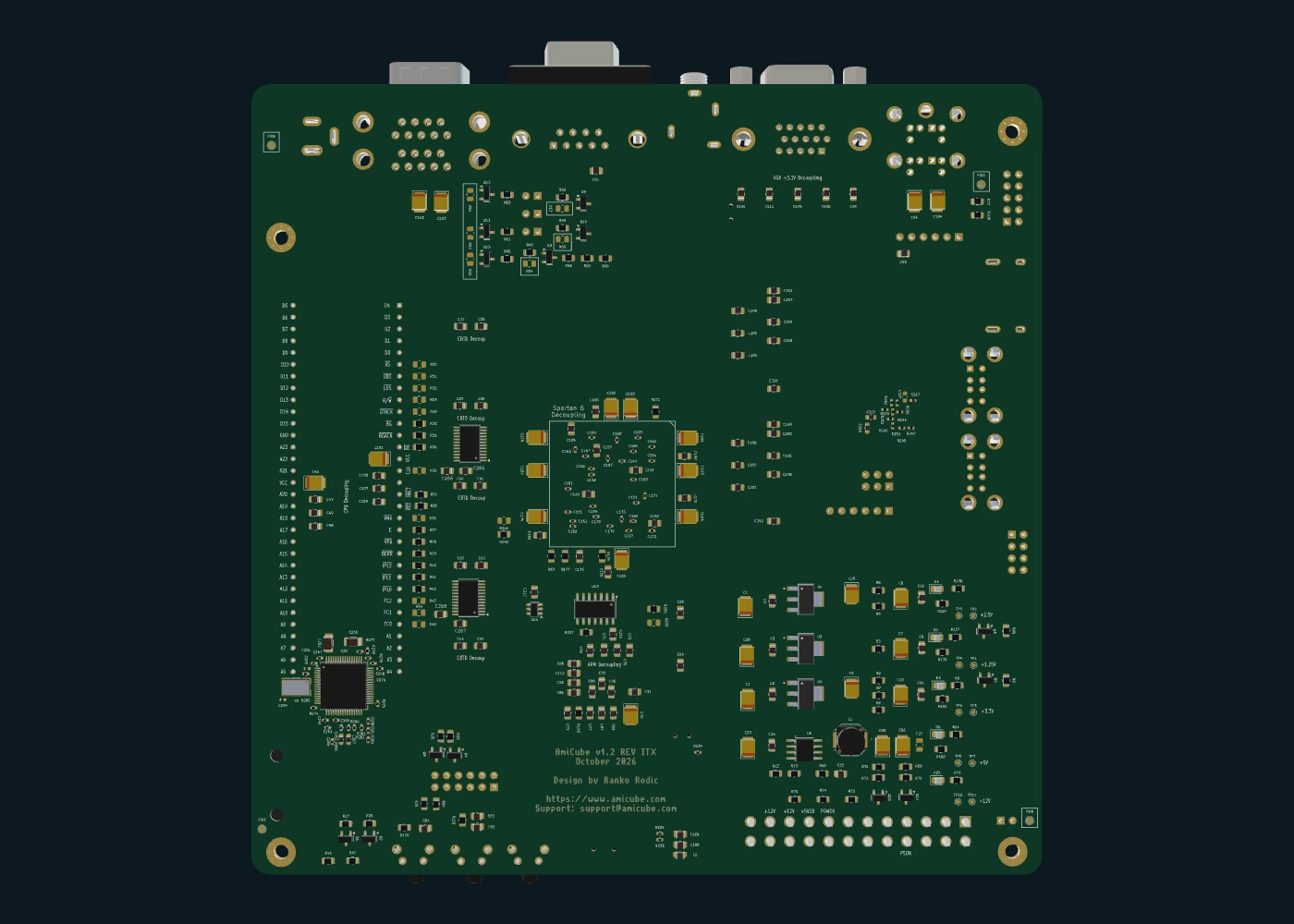
Current native AmiCube v1.2 underside with components, mounting holes and silkscreen170 MM / EIGHT LAYERS

MINI-ITX FOOTPRINT · CLASSIC CONNECTIONS

Every side has a purpose.

Dual floppy headers, PS/2, DB9 controllers and serial sit alongside HDMI, USB and Ethernet. An ATX supply connection and front-panel header bring the board into a complete system.

PCB outline
170 × 170 mm
Mounting
Four 3.2 mm holes
Construction
Eight copper layers
Open the bottom assembly drawing ↗
TWO INDEPENDENT MEMORY CHANNELS

Dedicated paths. Shared purpose.

Each SDRAM has its own 16-bit data bus, address, commands and clock. The two channels share power and ground.

CONNECTIONS ACROSS GENERATIONS

From floppy to Ethernet.

Explore all 18 connector groups in the port map, then turn the native model to see their physical positions.

Explore every connection ↗

Current v1.2 development hardware. The interactive model follows the saved PCB; its exploded view separates component groups for inspection. Core integration, timing and physical qualification remain in progress.

05 / THE ASSEMBLY BOOK

Good design.
Down to the details.

Start with top assembly, then turn the board over and explore its stackup, routing and power guides.

Open the 5-page board guide ↗

SELECT A DRAWING

Native engineering drawings
Development documentation

01 / 05

Board / top assembly

06 / WHERE WE ARE

Real hardware.
A continuing story.

CURRENT BOARD SNAPSHOT

AmiCube / v1.2

The routed native design includes two independent SDRAM channels and the complete translated 68000 bus. The model comes directly from the latest saved KiCad PCB.

Source revision 4bb9cf2 · native geometry throughout.
DOCUMENTED DESIGN

Five sheets. Every detail.

Top and bottom assembly, layer stackup, routing, power and buses. The current board-guide checks report clear ERC, DRC, connectivity and schematic parity.

Engineering checks document the design snapshot.
NEXT CHAPTER

Build. Test. Refine.

Core integration for the independent memory channels, timing and signal integrity, Ethernet software and prototype qualification.

Hardware and firmware validation continue together.
AmiCube / v1.2

A classic heart. A new dimension.

Explore the hardware ↑
Assembly drawingOpen PDF ↗
Enlarged assembly drawing

Use the PDF for vector detail and printing.